[Next] [Previous] [Up] [Top] [Copyright] [Books About Ethernet]

10.2 100BASE-TX Components

Network Medium


The 100BASE-TX media system is designed to allow segments of up to 100 meters in length when using data grade unshielded twisted-pair wire that has a characteristic impedance of 100 ohms and meets the EIA/TIA Category Five*1 wire specifications. Segments of 100BASE-TX are limited to a maximum of 100 meters to ensure that the round trip timing specifications are met. This is in contrast with the 10BASE-T media system, where the maximum segment length for the 10-Mbps link is mostly limited by signal strength.

For example, if you use high quality twisted-pair cable in a 10BASE-T segment, it's possible to reach segment lengths of approximately 150 meters with success. This is not true in the Fast Ethernet system, where the segment length for twisted-pair segments is set at a maximum of 100 meters for signal timing reasons. The EIA/TIA cabling standard recommends a segment length of 90 meters between the wire termination equipment in the wiring closet, and the wall plate in the office. This provides 10 meters of cable allowance to accommodate patch cables at each end of the link, signal losses in intermediate wire terminations on the link, etc.

There are twisted-pair Ethernet cable testers available that allow you to check the electrical characteristics of the cable you use, to make sure it meets the important electrical specifications in the standard. These specifications include signal crosstalk, which is the amount of signal that crosses over between the receive and transmit pairs, and signal attenuation, which is the amount of signal loss encountered on the segment.

The 100BASE-TX media system uses two pairs of wires, which means that four pins of the eight-pin (RJ-45 style) MDI connector are used to carry Ethernet signals.
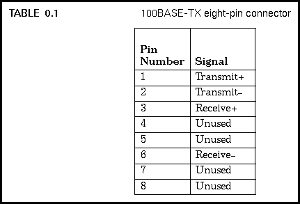
The transmit and receive data signals on each pair of a 100BASE-TX segment are polarized, with one wire of each signal pair carrying the positive (+) signal, and the other carrying the negative (-) signal.

The pin numbers used in the eight-pin connector for 100BASE-TX were changed from the ones defined in the ANSI TP-PMD standard, in order to conform to the wiring scheme already in use in the 10BASE-T standard. The ANSI standard uses pins 7 and 8 for receive data, whereas 100BASE-TX uses the same pins as the 10BASE-T system: 3 and 6. That way, a 100BASE-TX board can replace a 10BASE-T board, and be plugged into the same Category 5 wiring system without making any wiring changes.

The 100BASE-TX standard also accommodates shielded twisted-pair cabling with a characteristic impedance of 150 ohms. This type of cabling may be found in certain building cabling systems. If shielded twisted-pair cable equipped with 9-pin "D-type" connectors is used, the connector is wired according to the ANSI TP-PMD specifications: Pin 1: Receive (+), Pin 5: Transmit (+), Pin 6: Receive (-), Pin 9: Transmit (-).


Quick Reference Guide to 100BASE-TX - 09 SEP 95
[Next] [Previous] [Up] [Top] [Copyright] [Books About Ethernet]

Generated with CERN WebMaker